 English
 Deutsch
 Русский
 العربيّة
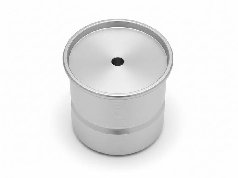
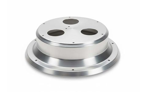
Buffer Cap
CNC Spun Buffer Cap for Machinery
Attributes
- MaterialCarbon Steel
- Thickness1.5mm
- Coatingwiredrawing
- SizeØ 96×150
CNC Spun Buffer Cap for Machinery - Technical Specification Sheet
1. General Information
Industry:
Machinery & Industrial Equipment Manufacturing
Product Designation:
Buffer Cap
Manufacturing Process:
CNC Metal Spinning with Precision Finishing
Base Material:
Q235B Carbon Structural Steel (Compliant with GB/T 700-2006)
2. Material Properties
- Yield Strength: ≥235 MPa
- Tensile Strength: 370–500 MPa
- Elongation: ≥26%
- Density: 7.85 g/cm³
- Melting Point: 1450–1500 °C
The selected Q235B carbon steel offers a balanced combination of strength, ductility, and impact resistance, making it suitable for buffering and protective applications under dynamic mechanical loads.
3. Dimensional Specifications
Wall Thickness:
1.5 mm
Tolerance: ±0.10 mm
Overall Dimensions:
Ø96 mm × H150 mm
Dimensional Accuracy:
- Manufactured in accordance with GB/T 1804-2000, tolerance class m
- Roundness deviation ≤0.20 mm
- Perpendicularity ≤0.15 mm/m
Surface Roughness:
Ra ≤0.8 μm after brushing
4. Surface Treatment
Finish Type:
Axial Wire Drawing (Brushed Finish)
The brushing process produces a uniform linear texture, enhancing surface aesthetics while improving wear resistance and reducing surface defects commonly associated with formed components.
5. Manufacturing Process Description
5.1 Forming Technology
The buffer cap is produced using CNC-controlled metal spinning, followed by precision wire drawing and secondary finishing operations.
This forming method ensures high material utilization, consistent wall thickness, and excellent structural integrity.
Key Spinning Parameters:
- Spindle speed: 800–1200 r/min
- Roller feed rate: 5–10 mm/s
- Single-pass deformation: 0.3–0.5 mm
- Total controlled deformation: 1.4–1.6 mm
These parameters guarantee uniform wall thickness and dimensional stability across the entire component.
5.2 Surface Brushing Parameters
- Brushing method: Mechanical axial wire drawing
- Line speed: 15–20 m/min
- Abrasive belt grit: #1200
- Texture depth: 0.05–0.10 mm
6. Raw Material Preparation
Carbon steel sheets undergo alkaline degreasing (50–60 °C, NaOH 5–8%, 10–15 min), followed by water rinsing, neutralization, and controlled drying at 70–90 °C for 15–20 minutes.
Material flatness is corrected using a precision leveling machine, achieving flatness ≤0.2 mm/m.
This process ensures clean, oxide-free surfaces, uniform grain structure, and stable forming performance during spinning.
7. CNC Process Control
- CAD/CAM software is used to generate optimized tool paths and G-code programs
- CNC spinning systems perform real-time dimensional monitoring of diameter, height, and wall thickness
- Data sampling frequency: 12 measurements per second
- Closed-loop control ensures high repeatability and process stability
The open-end interface is finished on a CNC lathe, achieving end-face perpendicularity ≤0.1 mm/m.
8. Post-Processing
- Mechanical deburring at 3000 r/min using #1500 abrasive wheels
- Compressed air cleaning to remove residual particles
- Final surface brushing and dimensional re-verification
All components undergo 100% dimensional confirmation after surface finishing.
9. Quality Assurance & Inspection
9.1 Standards Compliance
- ISO 9001:2015 Quality Management System
- GB/T 700-2006 Carbon Structural Steel Standard
Quality control covers incoming material inspection, in-process monitoring, and final product validation.
9.2 Raw Material Inspection
- Chemical composition verified by spectrometer (±0.05% accuracy)
- Mechanical properties tested using tensile testing equipment
- Ultrasonic testing (UT) confirms absence of internal defects such as porosity, inclusions, or cracks
9.3 In-Process Inspection
Five critical inspection stages are implemented:
Spinning Geometry Inspection
- Curvature conformity ≥98%
- Wall thickness measured circumferentially using ultrasonic gauges (±0.01 mm)
Dimensional Inspection
- Ø96 mm, H150 mm, and interface dimensions verified by CMM (±0.005 mm)
Surface Finish Inspection
- Visual inspection ensures uniform brushing without chatter marks or scratches
- Surface roughness measured using a contact roughness tester
Edge Condition Inspection
- Burr-free edges
- Chamfer radius R ≥1.2 mm
Internal Integrity Inspection
- Radiographic testing (RT) in accordance with JB/T 4730.2-2005, Quality Level II
9.4 Final Inspection
Sampling inspection is performed according to GB/T 2828.1-2012, AQL 2.5.
Qualified products are supplied with full traceability, including material batch, equipment ID, operator records, and production timestamps, accompanied by inspection reports and material certificates.
10. Production Capacity & Lead Time
Equipment Configuration:
- CNC spinning machines: 6 units
- Automatic wire drawing machines: 4 units
- CNC lathes: 3 units
Production Capacity:
- Approx. 120 pcs/day per equipment set (two shifts)
- Maximum monthly capacity: 7,200 pcs
Lead Time:
- Small batch (10–50 pcs): 4–6 working days
- Large batch (≥100 pcs): 8–12 working days
- Rush orders: 2–4 working days (subject to capacity prioritization)
11. Packaging & Delivery
Products are packed using anti-rust paper, pearl cotton, and reinforced cartons.
Each carton contains 50 units with internal separators to prevent collision damage.
Door-to-door logistics service is available, and customer-specified carriers or on-site delivery can be arranged with prior confirmation.
12. Customization Capability
Customization options include:
- Diameter range: Ø50–300 mm
- Height range: 50–250 mm
- Material grades: Q235A, Q355B, and equivalent carbon steels
- Surface treatments: painting, electroplating, and functional coatings
Technical feasibility evaluation is completed within 2 working days upon receipt of drawings and operating parameters.
13. Applications
13.1 Primary Applications
Used as buffering, protective, and sealing components for moving mechanical parts, including:
- Hydraulic rod ends
- Piston rods
- Guide rods
- Transmission mechanisms
- Robotic arm terminals
These buffer caps effectively absorb impact energy, protect component interfaces, and prevent dust ingress during motion.
13.2 Operating Conditions
- Temperature range: –20 °C to 120 °C
- Compatible media: hydraulic oil, lubricating oil, industrial air
- Rated buffering pressure: ≤1.0 MPa
Applicable to hydraulic machinery, pneumatic systems, automation equipment, conveying machinery, and construction machinery.
14. Extended Applications
Suitable for:
- New energy vehicle drivetrain systems
- Intelligent warehousing and AGV equipment
- Heavy-duty hydraulic machinery
- Agricultural machinery
- Rail transit equipment
The product provides reliable impact absorption, structural protection, and operational stability under high-frequency or heavy-load conditions.
15. After-Sales Service
- Warranty period: 18 months from acceptance
- Coverage includes dimensional deviation, material non-conformance, forming defects, surface damage, and buffering performance failure
- Free repair or replacement within warranty, including logistics costs
Post-warranty services include refurbishment, surface re-brushing, dimensional correction, and interface modification.
Long-term maintenance agreements are available for large-scale machinery projects.
Contact us and Request A Quote